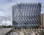

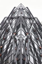
London, as a millennia-old metropolis and the former gravitational center of the world’s first industrialized imperial power, is a city of great juxtapositions in scale and style, a setting all the more pronounced by a labyrinthine network of streets crisscrossed with rail lines and disused canals. The Brunel Building, designed by Fletcher Priest Architects and located in the Paddington neighborhood just north of Hyde Park, embraces this contradictory morphology and industrial heritage with a dizzying diagrid of an exoskeleton and thoughtfully detailed spandrels.
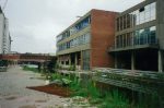
The 17-story tower is located adjacent to Paddington Station, the terminus of the defunct Great Western Railway, a great infrastructural scheme design by the prolific engineer and project namesake Isambard Kingdom Brunel. It is safe to say that Fletcher Priest’s design, in collaboration with the structural engineer and facade consultant Arup, lives up to that legacy of fine-tuned complexity. The project rises from a sliver of a plot sandwiched against the Paddington Canal and directly above lines servicing the London Underground, a constrained setting which required the tower’s three concrete cores—visible as a facade element and composed of silica-fumed high-flow concrete—to effectively thread the needle to a minimized foundation.
The first full-scale prototype of the Brunel Building’s facade and building system dates back to 2015 and was constructed in a warehouse in West London. Prototyping allowed for the design and engineering teams to weigh several jointing and connection approaches, as well as glazing options, prior to fabrication and installation. “The overall geometry of the steelwork and aesthetic approach were developed between Fletcher Priest and the structural engineer and did not change once contractors had been appointed,” said associate Chris Radley and founding partner Keith Priest. “However, we collaborated with the steelwork fabricator to optimize the design for specific loadings at each connection, within an overall logic to the way connections were expressed. This required architectural, structural and fabrication input to ensure every detail was thought through and agreed upon.”
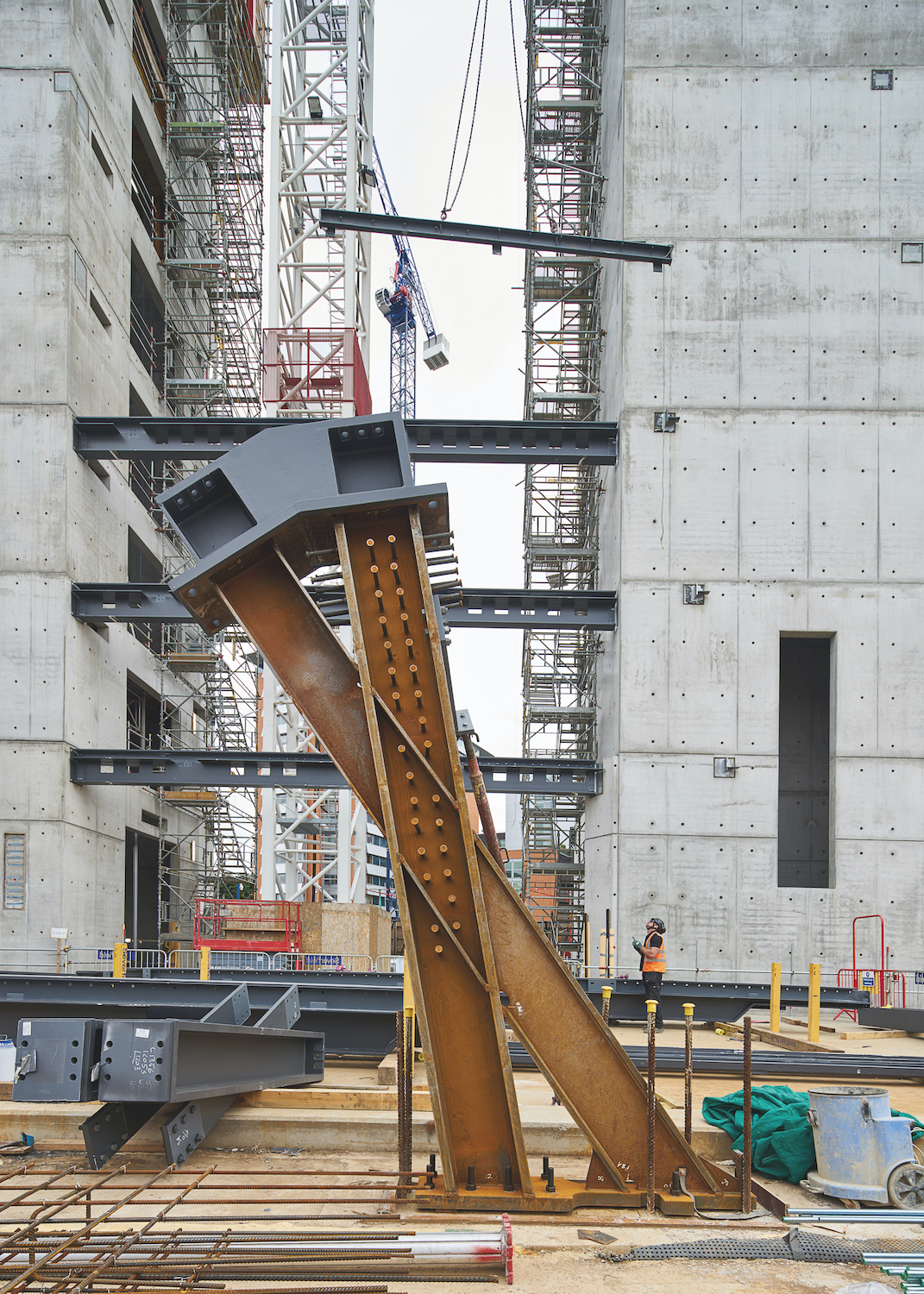
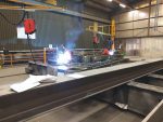
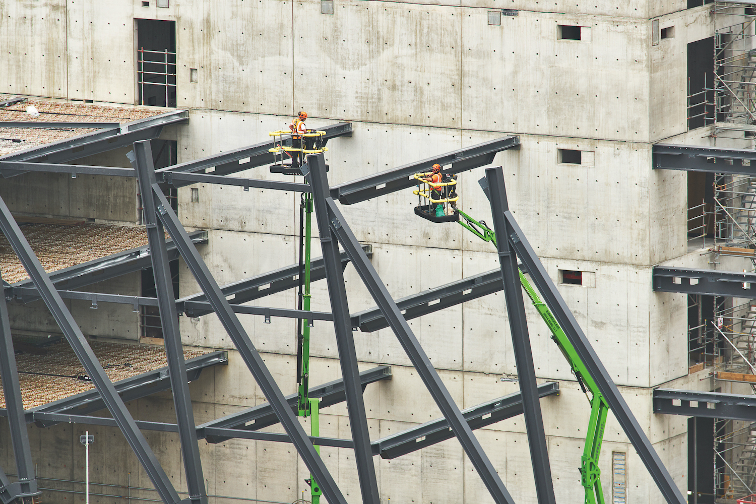
The steel columns and floor beams were manufactured by structural steel specialist Severfield at their plant in Yorkshire. Their installation began with the casting of connection plates within the concrete core, a procedure that required absolute precision to avoid unsightly repairs during the construction process, which was achieved through the projection of a 3D model on top of the concrete. The installation of the external grid and the floor beams occurred at three-story intervals, and the latter effectively tie the exoskeleton back to the primary structure and support the concrete floor plate.
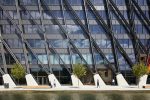
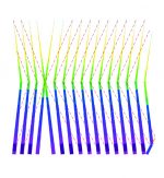
After several digital iterations, the design and structural teams settled on an approximately 20-foot spacing between the diagrid elements, which reduced the tonnage of steel used as well as the number of bespoke connections required. Beyond the structural, the steelwork also functions as a shading device with denser patterns corresponding to more exposed areas. The exoskeleton connections come in two forms; one handles major floor loads while the other connects bracing elements.
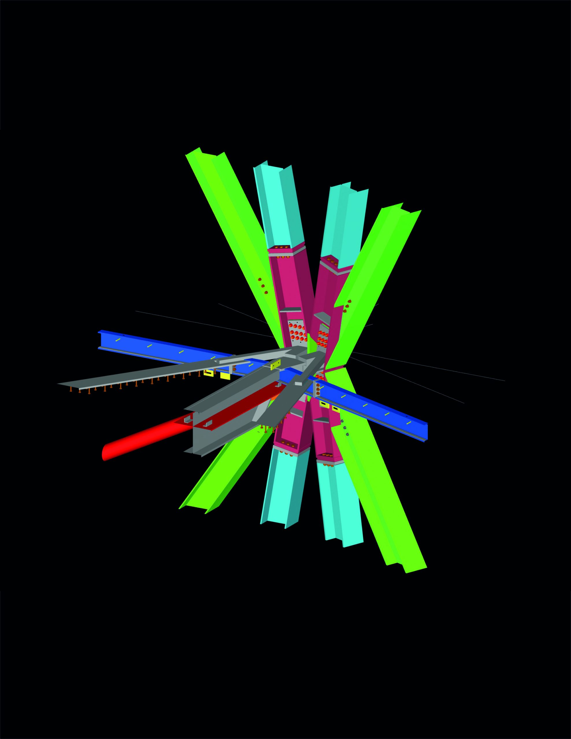
As one would expect, the sheer amount of steel found at the facade and its connection to the floor plate posed issues associated with thermal bridging and weathering. “In terms of the facade, the greatest challenges were related to the building structure being outside the facade line,” continued Radley and Priest. “These were overcome through a combination of early use and exchange of 3D models—to develop, assess, and coordinate the design —and a close and collaborative design and construction team. It was crucial to the success of the project that both the facade and steelwork contractors worked with the design team to resolve key details much earlier than would normally be the case.”
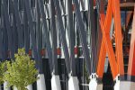
The unitized curtain wall backing the exoskeleton was fabricated and installed by Permasteelisa, and include an approximately four-and-a-half foot tall spandrel. The spandrel, treated with an X-shaped pattern, is intended to evoke Brunel’s truss design at the Clifton Suspension Bridge in Bristol.